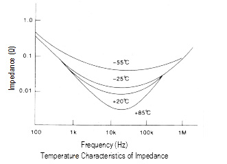
As shown at the next page, the impedance value varies with
temperature because the resistance of the electrolyte is strongly
affected by temperature.
Leakage current:
The dielectric of a capacitor has a very high resistance that does
not allow DC current to flow. However, due to the characteristics
of the aluminum oxide layer that functions as a dielectric in contact
with electrolyte, a small amount of current, called leakage current,
will flow to reform and repair the oxide layer when a voltage is
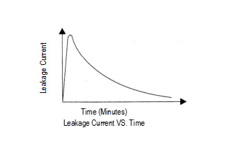
being applied. As shown below, a high leakage current flows to
charge voltage to the capacitor for the first seconds, and then
the leakage current will decrease and reach an almost steady-
state value with time.
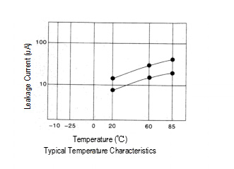
Measuring temperature and voltage influences the leakage current.
The leakage current shows higher values as the temperature and
voltage increase.
In general, the leakage current is measured at 20℃ by applying
the rated voltage to capacitor through a resistor of 1000Ω in
series, The leakage current is the value several minutes later
after the capacitor has reached the rated votage. The catalog
prescribes the measuring termperature and time.
Reliability
The bathtub curve:
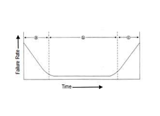
Aluminum electrolytic capacitors feature failure rates shown
by the following bathtub curve.
a) Infant failure period
This initial period accounts for the failures caused by
deficiencies in design, structure, the manufacturing process
or severe misapplications, In other words the initial failures
occur as soon as the components are installed in a circuit.
In the case of aluminum electrolytic capacitors, these failures
do not occur at customers' field because aging process
reforms an incomplete oxide layer, or eliminate the defective
parts at the aging process and the sorting process.
Misapplication of the capacitor such as inappropriate
ambient conditions, over-voltage, reverse voltage, or
excessive ripple current should be avoided for proper use
of the capacitor in a circuit.
b) Useful life period
The random failure period exhibits an extremely low failure
rate. These failures are not related to operating time but to
application conditions. During this period, non-solid aluminum
electrolytic capacitors lose a small amount of electrolyte. The
electrolyte loss shows as a slow decrease in capacitance
and a slow increase in tanδ and ESR. Non-solid aluminum
electrolytic capacitors still exhibit lower catastrophic failures
than semiconductors and solid tantalum capacitors.
c) Wear-out failure period
This period reflects a deterioration in the component
properties of the capacitor; the failure rate increases with
time, Non-solid aluminum electrolytic capacitors end their
useful life during this period.
Failure types:
The two types of failures are classified into catastrophic failures
and wear-out failures as following.
1) Catastrophic failures
This is a failure mode that destroys the function of the
capacitor like a short circuit or open circuit failure.
2) Wear-out failures
This is a failure mode where gradually deteriorates the
electrical parameters of the capacitor. The criteria of
judging the failures, vary with application and design factors.
Capacitance decreases and tanδ increases are caused
by the loss of electrolyte in the wear-out failure period. This
is primary due to loss of electrolyte by diffusion (as vapor)
through the sealing material. Gas molecules can diffuse out
through the material of the end seal. High temperature
increase the electrolyte vapor pressure within the capacitor
and the diffusion rate is therefore increased. This increases
internal pressure may cause the seal to bulge due to
temperature rise. This bulging may accelerate diffusion and
mechanically degrade the seal. Factors that can increase the
capacitor temperature, such as ambient temperature and
ripple current, can accelerate the wear-out phase of capacitor.


