Catalogs
Specifications in catalogs may be subject to change without
notice. For more details of precautions and guidelines for
aluminum electrolytic capacitors, please refer to Engineering
Bulletin No. 634A.
Structure of Aluminum Electrolytic Capacitors
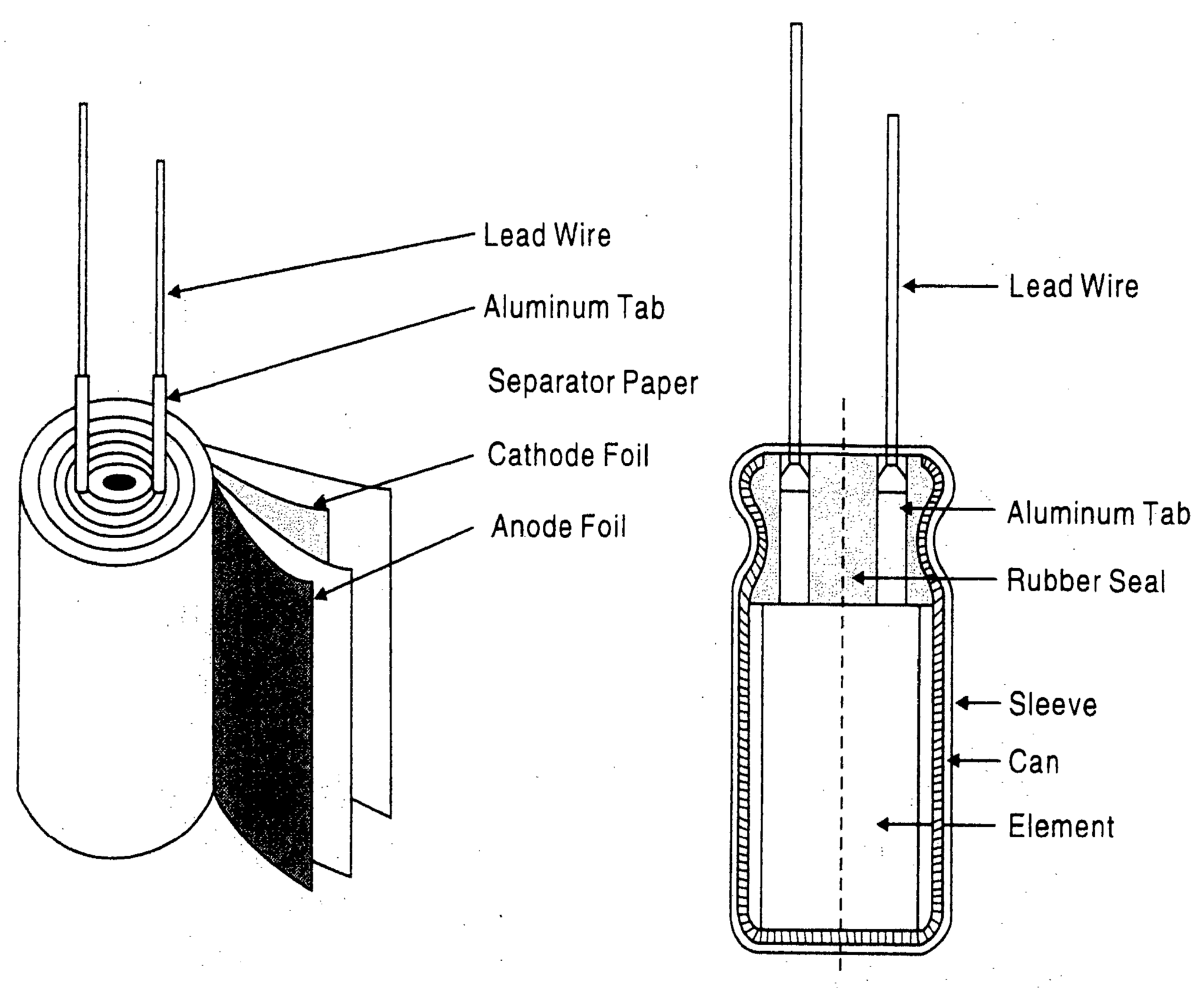
The aluminum electrolytic capacitor contains an internal element
of an anode foil, a cathode foil and paper separator rolled
together, impregnated with an electrolyte, then attached to
external terminals connecting the tabs with the anode or the
cathode foils and sealed in a can case.
Among various types of capacitors, an aluminum electrolytic
capacitor offers large CV to volume and features low cost.
The capacitance [C] of aluminum electrolytic capacitors, as well
as other capacitors, is expressed by the following equation:
C = 8.855 x 10⁻⁸ x εS/d (µF)
Where:
ε = Dielectric constant
S = Surface area of dielectric (cm2)
d = Thickness of dielectric (cm)
This equation shows that the capacitance increases in proportion
as the dielectric constant becomes high, its surface area becomes
large and the thickness of dielectric becomes thin, In aluminum
electrolytic capacitors the dielectric constant of an aluminum
oxide (Al2O3) layer is 8 to 10, which is not as high as compared
with the other types of capacitors. However, the dielectric layer
of the aluminum oxide is extremely thin (about 15Å per volt) and
the surface area is very large. An electrochemical formed
electrode foil makes the dielectric on the etched surface of
aluminum electrode foil. Electrochemical etching creates 20 to
100 times more surface area as plain foil. Therefore, an aluminum
electrolytic capacitor can offer a large capacitance compared
with other types.
Primary of Composition Material
Anode aluminum foil:
First, the etching process is carried out electromechanically with
a chloride solution which dissolves metal and increases the
surface area of the foil; forming a dense network like
innumerable microscopic channels. Secondly, the formation
process is carried out with a solution such as ammonium borate
which forms the aluminum oxide layer (Al2O3) as a dielectric at
a thickness of about 1.1 to 1.5nm/volt. The process needs to
charge more the rated voltage into the foil.
Cathode aluminum foil:
As in the first manufacturing process of the positive foil, the
cathode foil requires etching process. Generally, it does not
require the formation process; therefore, the natural oxide
layer of Al2O3, which gives a characteristic dielectric voltage
of 1.0 volts, is formed.
Electrolyte and separator:
In a non-solid aluminum electrolytic capacitor, the electrolyte,
an electrically conductive liquid, functions as a true cathode
by contacting the dielectric oxide layer. Accordingly, the
"cathode foil" serves as an electrical connection between the
electrolyte and terminal.
The separator functions to retain the electrolyte and prevent
the anode and cathode foils from short-circuiting.
Can case and sealing materials:
The foils and separator are wound into a cylinder to make an
internal element, which is impregnated with the electrolyte,
inserted into an aluminum can case and sealed. During the
service life of a capacitor, electrolyte slowly and naturally
vaporizes under electrochemical reaction on the boundary
of the aluminum foils. The gas will increase the pressure inside
the case and finally cause the pressure relief vent to open or
the sealing materials to bulge. The sealing material functions
not only to prevent electrolyte from drying out but also to allow
the gas to escape out of the can case in a controlled manner.
The Equivalent Circuit:
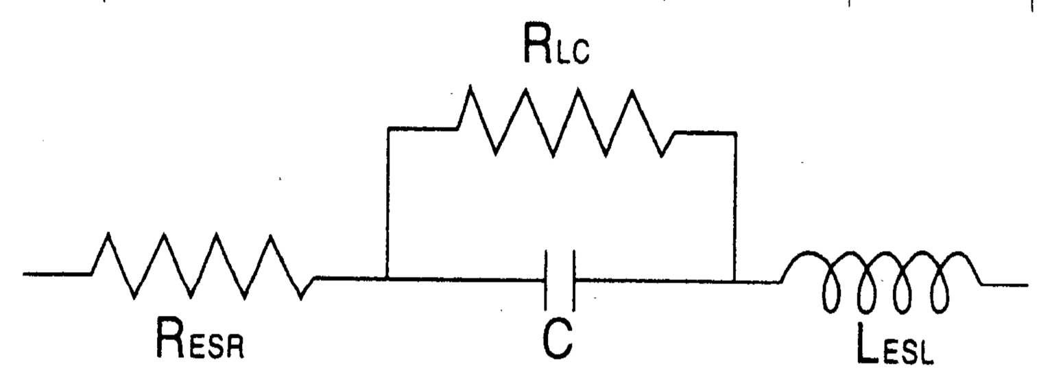
As the equivalent circuit of an aluminum electrolytic capacitor
is shown below, it forms a capacitance, a series resistance,
an inductance and a parallel resistance.
RESR = Equivalent series resistance (ESR)
RLC = Resistance due to leakage current
C = Capacitance
LESL = Equivalent series inductance
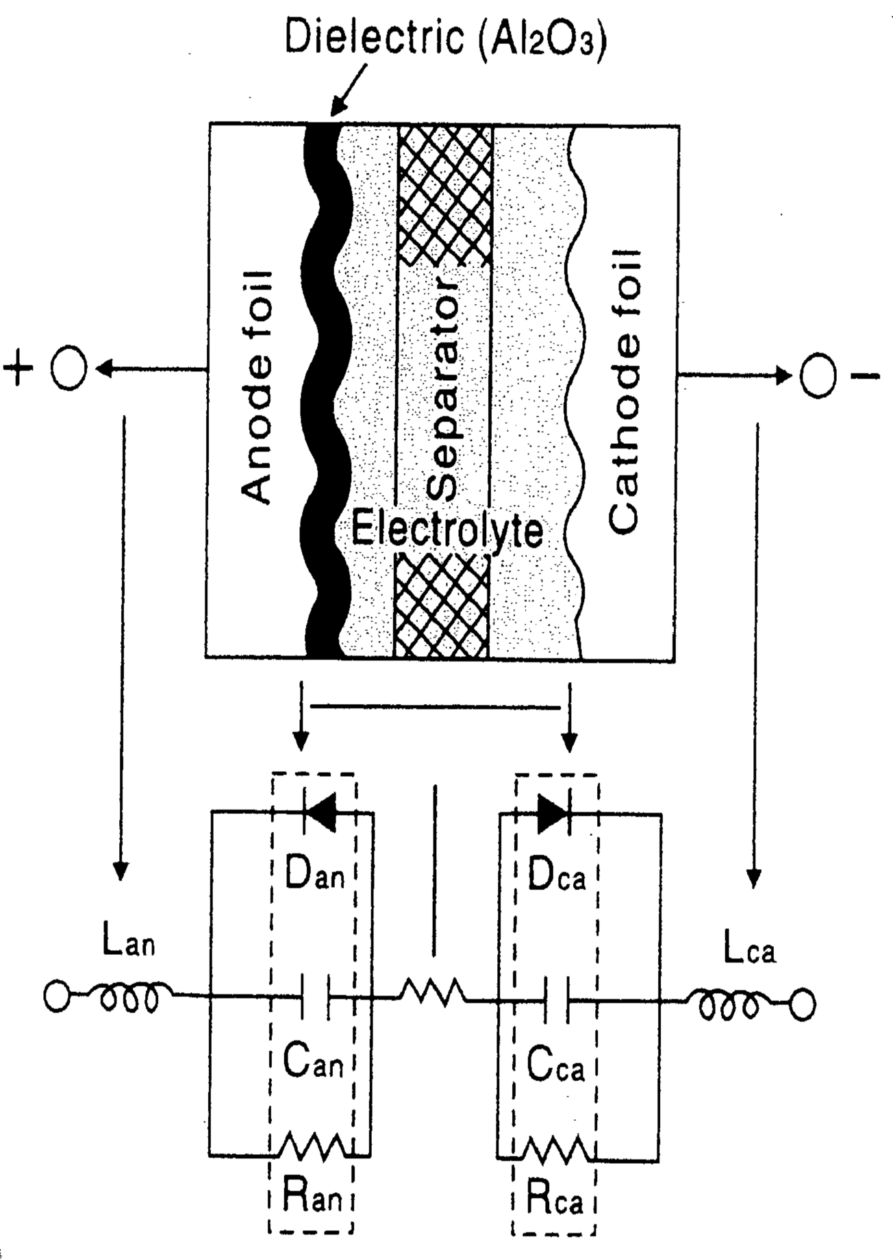
From a material composition point of view, the equivalent
circuit is subdivided as following:
Can, Cca = Capacitance due to anode and cathode foils
R = Resistance of electrolyte and separator
Ran, Rca = Internal resistance of oxide layer on anode & Cathode foils
Dan, Dca = Diode effects due to oxide layer on anode & Cathode foils
Lan, Lca = Inductance due to anode & cathode terminals


